Announcement

Collapse
No announcement yet.

Xkill Super build

Collapse
X
Collapse
Currently Active Users Viewing This Thread: 0 (0 members and 0 guests)
 
  • Filter
  • Time
  • Show
Clear All
new posts

  • Xkill
    replied
    Let me just show the last update for this is as it has already hit the rocks a few times.

    Decided to cut new wheels from 3mm G10 and went to a different design front and rear. Why? Because I can and I liked both designs....
    Also designed the weight holders.
    They have tungsten in the lower part and Brass on the upper. Max weight is 304gr per side.

    Click image for larger version

Name:	Photo Resizer 2021_05_12_11_03_28.jpg
Views:	136
Size:	168.8 KB
ID:	783

    To hold the weight hangers in place I have this 3d printed part with 2 screws on opposite sides.
    Click image for larger version

Name:	Photo Resizer 2021_05_12_11_04_17.jpg
Views:	127
Size:	71.5 KB
ID:	784

    To be sure they dont rotate I makr the place for these screws and just drill 1 or 2mm deep. Just be careful not to drill to the bearing pocket.
    Click image for larger version

Name:	Photo Resizer 2021_05_12_11_04_50.jpg
Views:	127
Size:	59.0 KB
ID:	785

    And that's that!
    Click image for larger version

Name:	Photo Resizer 2021_05_12_11_05_19.jpg
Views:	133
Size:	178.0 KB
ID:	787

    At this point I worked on the electronics (not much to see there).
    In the end I am running a HH SHV500 on the front and a Futaba A700 on the rear (both of them running 3S), HH BR mini and the 35t HH motors.

    Click image for larger version

Name:	Photo Resizer 2021_05_12_11_43_53.jpg
Views:	129
Size:	92.8 KB
ID:	792
    Click image for larger version

Name:	Photo Resizer 2021_05_12_11_44_16.jpg
Views:	125
Size:	115.0 KB
ID:	793
    Click image for larger version

Name:	Photo Resizer 2021_05_12_11_44_28.jpg
Views:	128
Size:	94.6 KB
ID:	794

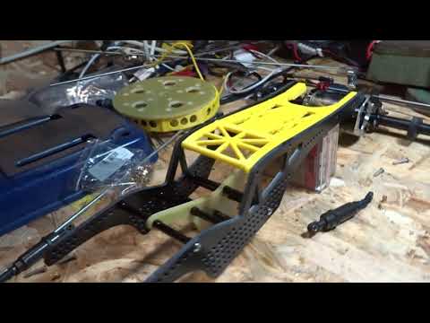
    Next I started working on the chassis skid.
    Almost 2h after I got it done!

    From this....
    Click image for larger version

Name:	Photo Resizer 2021_05_12_11_05_31.jpg
Views:	128
Size:	108.3 KB
ID:	788
    .....to this
    Click image for larger version

Name:	Photo Resizer 2021_05_12_11_05_48.jpg
Views:	124
Size:	105.5 KB
ID:	789

    Also made front and rear skids.
    In the front it will hold the battery as well.

    Click image for larger version

Name:	Photo Resizer 2021_05_12_11_06_01.jpg
Views:	129
Size:	140.7 KB
ID:	790

    Looks nice under the sun!

    Click image for larger version

Name:	Photo Resizer 2021_05_12_11_06_32.jpg
Views:	119
Size:	354.5 KB
ID:	791
    Final weight of the pig:
    Just over 3.4Kg with a fully loaded front and no weight on the rear.


    Click image for larger version

Name:	Photo Resizer 2021_05_12_11_44_41.jpg
Views:	121
Size:	136.1 KB
ID:	795

    And some bonus shots

    Click image for larger version

Name:	Photo Resizer 2021_05_12_11_06_41.jpg
Views:	126
Size:	151.4 KB
ID:	796
    Click image for larger version

Name:	Photo Resizer 2021_05_12_11_06_53.jpg
Views:	115
Size:	173.0 KB
ID:	797

    After about 5 long duration packs of 1100 mah (plan on running 650 packs but these ones were borrowed to me) I can say I really like using this rig and adapted well to the rear steer, even if sometimes I still have to think about where I want to go!

    I also didn't like the design of the chassis skid and eventually removed it.
    I will try a different design.

    I will probably put longer shocks in the front to try something out...

    And, finally....
    I broke it already!!!

    The front right welded shaft didn't last long....
    I have a plan to fix it/improve it but I need some time and lathe work....

    I will try to come up with some videos in the future.


    Attached Files

    Leave a comment:


  • Xkill
    replied
    Latest Super Updates.
    I have tires and I also have the temporary links made.
    I will use 5mm Ti on the lower links and 4mm on the top links.


    Leave a comment:


  • Xkill
    replied
    When I did my 2.2 pro I made a 2mm plate with holes on it and I also cut an extra piece (spare), because I was not sure it would hold the abuse.
    7 years of abuse after it's still the OG piece...

    This will be 4mm without any holes so I think it will hold up.
    If not I will cut another one because I didn't do a spare one this time...

    Leave a comment:


  • Curtaroni
    replied
    Do you think the center piece is going to be strong enough to take the torsion brought by a super?

    Leave a comment:


  • Xkill
    replied
    I hate building links!...
    I dont have a setup table for a Super so I made on the desk.
    Axles are fixed to the table with some wood screws.

    I am building the links with the rig at full bump.
    So far I'm using traxxas bigbores but I will have to solve the issue of preload of the springs.

    Leave a comment:


  • Xkill
    commented on 's reply
    Yes, that is my electronics tray.
    Maybe I'll do something similar on the Super, I will see what space I have to work with once I make links.
    I think the servos will be fine...
    Also I don't have a programmer for the futabas so the strengthener would also mean buying that.

  • crawlercon
    commented on 's reply
    Sorry, took me a while to get back here. That a pretty cool concept. I'm guessing the lexan at the right is the front, and an electronics tray? I'm interesting in how the servos work without torque multipliers too. On my super the rear seems ok with the Hitec servos and strengtheners, but the front seem a little lacking. I finally bought the farm and got some Futaba A700s. I'll probably just throw one on the front and see how it does. If their advertised stats are accurate that is a hell of a strong servo, and doesn't change much as the battery runs down. I'd like to see how it compared to a Holmes servo powered on 4s. A700 might handle full 3s, some people say they run that way, but I doubt it will handle 4s. Just see if it gets hot I guess.
    Last edited by crawlercon; 12-19-2020, 09:46 PM.

  • Xkill
    replied
    I will be running the futaba with ou servo stregthener and see how they go about...
    They will be on 3s straight, no bec.

    This is how my "skid less" pro looks like.
    The super will be the same.

    Click image for larger version

Name:	IMG_20201127_181223.jpg
Views:	180
Size:	80.4 KB
ID:	644Click image for larger version

Name:	IMG_20201127_181213.jpg
Views:	182
Size:	114.4 KB
ID:	645Click image for larger version

Name:	IMG_20201127_181238.jpg
Views:	182
Size:	151.1 KB
ID:	646

    Its only a bit of lexan so the rodends wont get stuck on the rocks.
    Its 25mm wide at the center and IMO works very well.

    Leave a comment:


  • crawlercon
    replied
    Looking good. You planning on running servo strengtheners or do you think you can get aways without them? Can you post a couple photos of your Pro so we can see how your skidless design works?

    Leave a comment:


  • apehanger
    replied
    cool design !

    "I made a upper brace for the chassis but the home printed ABS decided to shrink and doesn't fit..."

    Yes I know, ABS shrink a little bit! Measure the component and for the next 3d-print enter the difference in the slicer, for example print 2% bigger.

    Leave a comment:


  • Pat13
    replied
    Very cool , good job

    Leave a comment:


  • Xkill
    replied
    Work on the Super continues!

    While rebuilding the front axle I noticed the original CVD was really worn out.
    I could not even take it apart and it was binding a bit.
    The long term plan was to move to Universals at some point so that plan went to Fast Track.
    It would have been better if I had a lathe but so is life....
    They didn't turn out too bad and griding and bad lighting is the best remedy for crappy welds.
    I hope they will hold.


    Click image for larger version

Name:	IMG_20201116_132429.jpg
Views:	344
Size:	107.0 KB
ID:	626

    Click image for larger version

Name:	IMG_20201116_161801.jpg
Views:	330
Size:	82.6 KB
ID:	627

    Click image for larger version

Name:	IMG_20201116_165430.jpg
Views:	330
Size:	140.3 KB
ID:	628

    After that I had to "adjust" the hubs that I am going to use on this.

    Click image for larger version

Name:	IMG_20201124_172307.jpg
Views:	336
Size:	98.2 KB
ID:	629

    Then it was off to the CNC!

    Click image for larger version

Name:	IMG_20201123_160359.jpg
Views:	330
Size:	111.5 KB
ID:	630

    Wheels and chassis were cut.

    Click image for larger version

Name:	Photo Resizer 2020_11_26_07_58_25.jpg
Views:	323
Size:	51.4 KB
ID:	631

    Click image for larger version

Name:	Photo Resizer 2020_11_26_07_58_36.jpg
Views:	338
Size:	76.5 KB
ID:	632

    Chassis turned out very well!
    I'm happy with it.
    I can move the lower piece for a more front or central bias.
    For now I think I will start with a more conventional setup.

    Click image for larger version

Name:	Photo Resizer 2020_11_26_07_55_06.jpg
Views:	370
Size:	39.7 KB
ID:	633

    Click image for larger version

Name:	Photo Resizer 2020_11_26_07_57_55.jpg
Views:	326
Size:	35.2 KB
ID:	634

    Click image for larger version

Name:	Photo Resizer 2020_11_26_07_58_12.jpg
Views:	331
Size:	42.1 KB
ID:	635

    I made a upper brace for the chassis but the home printed ABS decided to shrink and doesn't fit...

    Click image for larger version

Name:	Photo Resizer 2020_11_26_07_58_49.jpg
Views:	338
Size:	35.8 KB
ID:	637

    This might not be the final color setup for the wheels and chassis but you get the idea...

    Click image for larger version

Name:	Photo Resizer 2020_11_26_07_59_00.jpg
Views:	337
Size:	76.1 KB
ID:	636


    I will be using a 3D printed, all in one, spacer and back ring.
    This might not be the lightest (I can still work on that), but it's very simple and cheap.
    Only 4 screws on are enough for a very stiff assembly.
    Disadvantage is that the width can't be changed easily....

    Click image for larger version

Name:	Photo Resizer 2020_11_26_07_59_11.jpg
Views:	347
Size:	42.3 KB
ID:	638

    Shes gonna be a PIG!!!
    150g per wheel without the insert and tire!!!

    Click image for larger version

Name:	IMG_20201123_163121.jpg
Views:	328
Size:	102.2 KB
ID:	639

    Updates will take some time now but I'm happy with where this project is now.


    Attached Files

    Leave a comment:


  • Xkill
    replied
    Got very Lucky!
    Even if the axle was looking and spining without a problem one bearing had graneded itself.

    Click image for larger version

Name:	IMG_20201113_135359.jpg
Views:	576
Size:	78.0 KB
ID:	602 ​​​​​​The bearing balls were not found, probably in the midle of all the grease that I took out.

    Then I had the problem of removing the old bearings.
    Only with the heat gun I managed to take them out.

    Click image for larger version

Name:	IMG_20201113_135125.jpg
Views:	573
Size:	85.0 KB
ID:	603 Only one gear has some marks but they will survive.
    After all, its a bully v1!

    Leave a comment:


  • Xkill
    replied
    The weight before I took them apart.


    Click image for larger version

Name:	IMG_20201105_230208.jpg
Views:	373
Size:	181.8 KB
ID:	599Click image for larger version

Name:	IMG_20201105_230220.jpg
Views:	358
Size:	188.9 KB
ID:	600
    I could still cut a little bit more but it would probably be less than 10g per axle and I'd stay with some gears exposed.
    Meaning I'd have to build a plastic cover....
    Sóõ I dont think I'm gona bother with it.
    Attached Files
    Last edited by Xkill; 11-12-2020, 04:58 AM.

    Leave a comment:


  • Xkill
    replied
    Whoever machined my bully axles did a great job!
    The gears looks awesome!

    Click image for larger version

Name:	Photo Resizer 2020_11_11_02_44_19.jpg
Views:	390
Size:	42.5 KB
ID:	594

    Click image for larger version

Name:	Photo Resizer 2020_11_11_02_45_03.jpg
Views:	377
Size:	50.7 KB
ID:	593

    Need to clean everything and put it together before I start loosing parts in the Empire of Dirt (Aka my desk).

    Leave a comment:

Working...
X